.jpg)
Close the front door, open the side door (or open the front door, close and press the front door with the door switch), then press the reset button, and then press the start button (this is an unconventional operation, please pay attention to safety!), and observe whether the brake block circled in Figure 1 has been hit.
If hit. You can apply easily discoloring pigments (such as chalk, red lead, etc.) to the positions where the brake block and upper and lower ingot parking rods are hit. If discoloration occurs at any position, it indicates that there is a problem with the corresponding upper or lower ingots. First, eliminate the issue of brake blocks not being adjusted correctly (please refer to relevant articles on brake switch adjustment methods for details).
There are two reasons for the upper spindle brake.
The first type is excessive wire placement on the ingot. The reasons are as follows: 1. Insufficient tension on the upper ingot, which is also the main reason. Increase tension (please refer to Chapter 10, page 20 of the manual, and refer to the table for selecting tension spring specifications). 2. The upper spindle ratchet and upper spindle claw are severely worn and cannot be stuck. 3. The upper spindle ratchet is eccentric and severely deformed. 4. The tension seat on the upper ingot is not installed correctly, causing the edge of the upper ingot claw and the upper ingot ratchet to not reach a balanced state (as shown in Figure 2, the entire upper ingot claw edge should be buried in the bottom of the upper ingot ratchet teeth). The angle of the upper ingot claw can be changed by moving the tension seat back and forth.

The second type is that the upper ingot cannot release the silk thread (as shown in Figure 3, when the silk thread cannot be released, the tension lever of the upper ingot will be pulled to the position circled in Figure 3, and the plate type parking rod will be pressed down, thereby pressing down the upper ingot parking rod). This situation generally manifests as: slightly increasing the tension will cause the wire to break, and decreasing tension will cause the brake to brake. There are several reasons for this: 1. Misalignment of thread (a situation that can easily occur when the thread is hard, it is recommended to hold it with one hand and thread it with the other hand); 2. Stacked wire (the distance between parallel and parallel wires is too small, causing the wire to break and become tangled); 3. The two ends of the silk thread on the merging reel are concave and sandwiched; 4. The surface of the silk thread is rough. (Solution: Please refer to the relevant articles on the usage tips of the wire tying machine. If it still cannot be solved, please replace the thread.)

There are two reasons for the lower spindle brake.
The first option is to place too much wire in the lower ingot (in general, placing too much wire often leads to wire breakage. For details, please refer to the relevant articles on determining the cause of wire breakage). There are several reasons for this: 1. The distance between parallel wires is too wide; 2. The weaving pitch is large. (Please choose a lower spindle claw pressure spring with a thicker wire diameter)
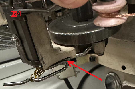
The second type is that the lower ingot cannot release the wire (the tension of the lower ingot is pulled to the position shown in Figure 4, pressing the lower ingot claw to the bottom, causing the lower ingot parking rod to extend towards the outer cam direction). There are several reasons for this: 1. Smashing (a situation that can easily occur when the thread is hard, it is recommended to hold it with one hand and thread it with the other hand); 2. Stacked wire (the distance between parallel and parallel wires is too small, causing the wire to break and become tangled); 3. The two ends of the silk thread on the merging reel are concave and sandwiched; 4. The surface of the silk thread is rough. (Note: Only relatively tough silk threads will have the phenomenon of brake when lowering the ingot. Generally, silk threads often break when lowering the ingot due to the above reasons).

If the brake switch is not activated, please check the following positions:
1. Is there any wire (or other metal object) touching the sensing copper rod behind the machine head on the small square frame, as shown in Figure 5.

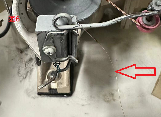
2. Is there any wire hanging on the lower ingot, hitting the copper rod, as shown in Figure 6.

3. Is there any thread hanging on the sensing ring of the suspension rod, as shown in Figure 7.

If the above issue still cannot be resolved, please contact our after-sales service department.
.png)
